Hydronic floor heating has emerged as a premier solution for achieving unparalleled indoor comfort and energy efficiency. As a highly effective radiant heating system, it distributes warmth evenly across living spaces, eliminating cold spots and reducing airborne dust associated with forced-air systems. However, the successful implementation of a hydronic floor heating system is a meticulous process, demanding expert planning, precise execution, and rigorous quality control.
This article delves into the comprehensive journey of a hydronic floor heating installation, from the initial quotation and detailed design finalization to the critical stages of system calibration and client handover. We will explore each phase, including project coordination, in-depth floor composition analysis, intricate circuit design and system calculations, the essential approval process, and the crucial specification of equipment and electrical requirements. Furthermore, we will detail the on-site coordination, the systematic scheduling and execution of installation phases, leading up to the final startup, calibration, and even pre-winter checks, ensuring a flawless and optimally performing heating solution for years to come.
What is Hydronic Floor Heating
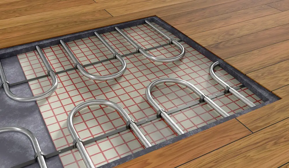
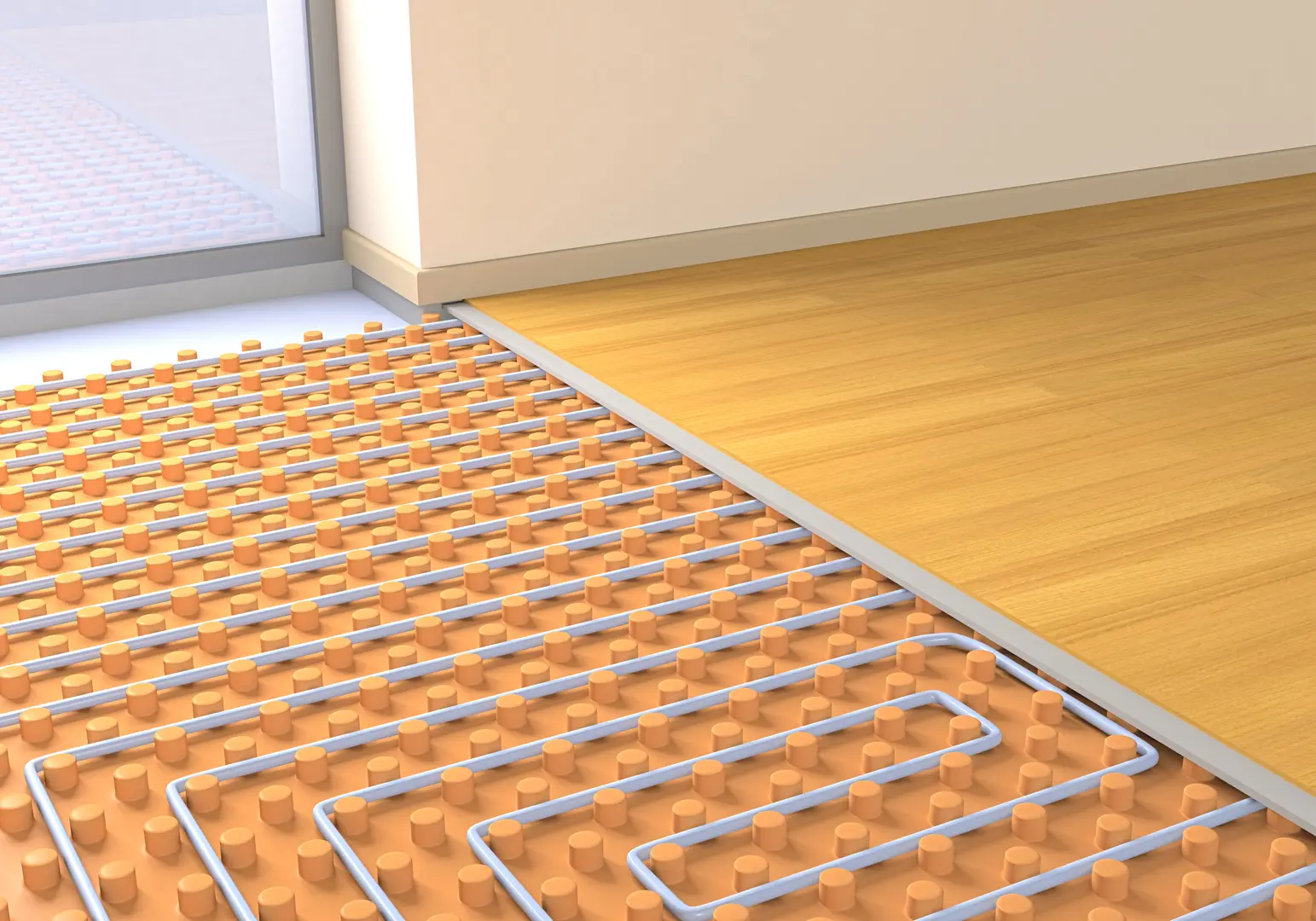
Hydronic floor heating, also known as radiant floor heating, is a system that circulates heated water through a network of pipes installed beneath your floor. This heated water, typically warmed by a boiler, heat pump, or even solar water heaters, then radiates warmth upwards through the floor surface, directly heating the objects and people in the room rather than just the air. This “radiant” heat is similar to the warmth you feel from the sun and offers a uniquely comfortable and consistent indoor climate.
Benefits of Hydronic Floor Heating
- Superior Comfort and Even Heating: Unlike forced-air systems that can create drafts and hot/cold spots, hydronic heating provides uniform warmth from the floor up, ensuring a consistent and comfortable temperature throughout the room. This often allows for lower thermostat settings while maintaining comfort, leading to energy savings.
- Improved Indoor Air Quality: As there are no fans or ducts circulating air, hydronic systems do not distribute dust, allergens, pet dander, or other airborne particles, making them an excellent choice for individuals with allergies or respiratory sensitivities.
- Quiet Operation: Hydronic systems operate virtually silently, eliminating the noise associated with forced-air furnaces and ductwork, such as air conditioning and HVAC systems.
- Energy Efficiency: Water is a highly efficient medium for heat transfer. Hydronic systems can be very energy-efficient, especially when paired with efficient heat sources like heat pumps or solar, and they eliminate duct losses common in forced-air systems.
- Design Flexibility: With no visible radiators or vents, hydronic floor heating offers greater flexibility in furniture placement and interior design.
- Versatility: Hydronic systems can be used with a wide range of floor coverings, including tile, stone, concrete, and even some types of wood flooring (with appropriate considerations). They can also be zoned to allow for individual temperature control in different areas of a home.
When and Where Hydronic Floor Heating Should Be Used
Hydronic floor heating is an ideal choice for:
- New Construction and Major Renovations: The installation process is most straightforward during the initial building phase, allowing for seamless integration into the floor structure.
- Whole-House Heating: Hydronic systems are highly effective at providing consistent and efficient heating for entire homes or large areas.
- Homes with Hard Surface Flooring: It’s particularly beneficial in rooms with tile, stone, or polished concrete floors, as these materials can otherwise feel cold underfoot.
- Environments Prioritizing Comfort and Air Quality: Homes where occupants suffer from allergies or prefer a quiet, gentle heat will greatly benefit.
- Areas with Access to Efficient Heat Sources: Homes with natural gas, access to renewable energy sources like solar, or where heat pumps are viable, can maximize the energy efficiency of hydronic systems.
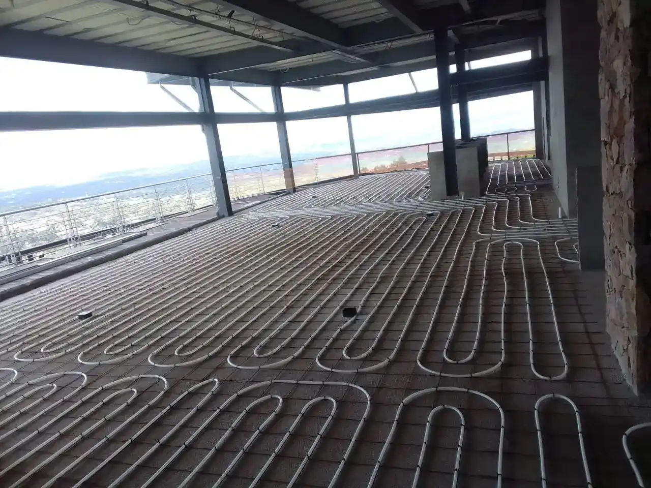
- Commercial and Institutional Buildings: The benefits of energy efficiency and comfort extend to larger spaces like offices, schools, and healthcare facilities.
Installation
It is essential to be included in the project from the earliest stages to prevent unnecessary remedial work and ensure seamless integration of the heating system into the overall construction process. These are the main steps and sequence of planning and installing hydronic floor heating systems:
1. Quotation and Acceptance
Present the quotation to the client and obtain formal acceptance, including a signed document and Phase 1 deposit.
2. Project Coordination & Design Finalisation
In collaboration with the client, architect, and structural engineer, finalise the floor composition, equipment placement, zone controls, thermostat locations, and routing of supply lines from the plant to designated manifold positions.
3. Floor Composition Analysis
Confirm the final floor buildup and finished floor heights by assessing possible cross-sections. This step is crucial for optimizing thermal efficiency and minimising radiant heat loss through the slab. Possible floor compositions include:
Insulation of top of the concrete slab.
Floor Makeup without insulation
Vermiculite Screed Insulation
4. Circuit Design & System Calculations
Develop a comprehensive circuit design based on floor construction, equipment placement, and joinery details. This design incorporates load, flow, and pressure drop calculations. Supporting documentation includes (Examples for Illustrative purposes only):
System Design Layout
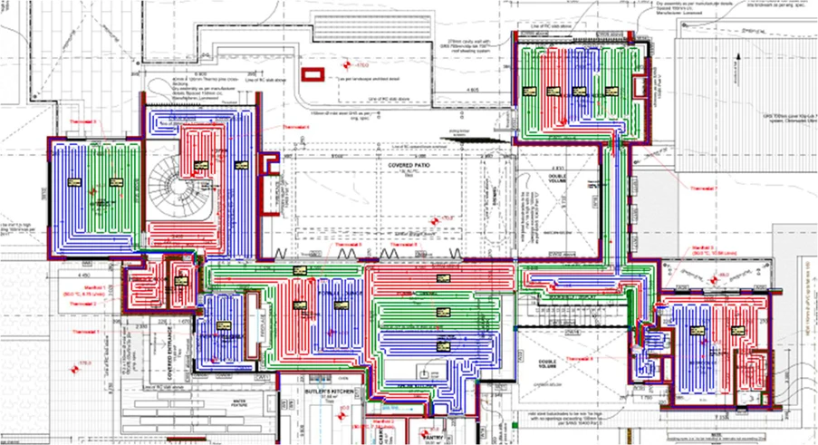
Fig 1.1 – Example System Design Layout
Flow Reports
| Water Temperature (49°C) | |||||||||||
| Manifold 1 (49°C, Stainless Steel, 7 Circuits) | |||||||||||
| Circuit | Rooms Served | Total Length | Tube Spacing | Area Covered | Tubing | Flowrate | Head Loss1 | Temp Drop2 | Load3 | Actuator | |
| A-1 | Room A-14 | 34.7 | 6.3 | Barrier PEX 16mm | 1.52 | 3.3 | 10.0 | 1,014 | No | ||
| A-2 | Room A-19 | 59.5 | 11.9 | Barrier PEX 16mm | 1.95 | 8.7 | 10.0 | 1,316 | No | ||
| A-3 | Room A-18 | 67.3 | 11.9 | Barrier PEX 16mm | 1.97 | 10.0 | 10.0 | 1,317 | No | ||
| A-4 | Room A-16 | 73.0 | 11.7 | Barrier PEX 16mm | 2.12 | 12.4 | 10.0 | 1,426 | No | ||
| A-5 | Room A-17 | 38.8 | 6.0 | Barrier PEX 16mm | 1.38 | 3.1 | 10.0 | 908 | No | ||
| A-6 | Room A-20 | 54.0 | 9.8 | Barrier PEX 16mm | 1.46 | 4.8 | 10.0 | 998 | No | ||
| A-7 | Room A-15 | 59.0 | 11.9 | Barrier PEX 16mm | 2.39 | 12.4 | 10.0 | 1,614 | No | ||
| Total | – | 386.2 | 69.7 | – | 12.79 | 12.4 | – | 8,593 | 0 | ||
| (1) Head loss for circuit tubing only. (2) Design Temp Drop (Estimated Actual Drop). (3) Required Load. Includes panel back losses. Does not reflect maximum capacity of the circuit. | |||||||||||
| Manifold 2 (49°C, Stainless Steel, 4 Circuits) | |||||||||||
| Circuit | Rooms Served | Total Length | Tube Spacing | Area Covered | Tubing | Flowrate | Head Loss1 | Temp Drop2 | Load3 | Actuator | |
| A-8 | Room A-07 | 106.6 | 26.7 | Barrier PEX 16mm | 5.61 | 99.4 | 10.0 | 3,790 | No | ||
| A-9 | Room A-06 | 101.0 | 21.5 | Barrier PEX 16mm | 4.00 | 52.1 | 10.0 | 2,759 | No | ||
| A-10 | Room A-06 | 103.6 | 22.1 | Barrier PEX 16mm | 4.07 | 22.0 | 10.0 | 2,773 | No | ||
| A-11 | Room A-07 | 74.8 | 16.2 | Barrier PEX 16mm | 3.39 | 29.0 | 10.0 | 2,281 | No | ||
| Total | – | 386.0 | 86.6 | – | 17.07 | 99.4 | – | 11,602 | 0 | ||
| (1) Head loss for circuit tubing only. (2) Design Temp Drop (Estimated Actual Drop). (3) Required Load. Includes panel back losses. Does not reflect maximum capacity of the circuit. | |||||||||||
| Room Heating Summary | |||||||||||||||
| Embedded Suspended Slab | |||||||||||||||
| Zone # | Room Name | Heating Type | Floor Area | Heated Area | Manifold # | Tube Size | RH Circuits1 | Tube Spacing | Tubing In Room | Floor Cover RV. | Required Temp. | Unit RH Load | RH Load2 | Supplemental | Total Load3 |
| Zone 101 | Room A-01 | RH | 159.9 | 128.3 | Manifold 3 | 16mm | 7 | 201 | 638.0 | 0.09 | 40 | 116.9 | 14,996 | 0 | 14,996 |
| Zone 101 | Room A-02 | RH | 33.2 | 25.7 | Manifold 8 | 16mm | 1 | 264 | 97.5 | 0.09 | 47 | 150.0 | 3,860 | 0 | 3,860 |
| Zone 101 | Room A-03 | RH | 56.2 | 52.6 | Manifold 8 | 16mm | 2 | 189 | 278.0 | 0.09 | 42 | 130.1 | 6,848 | 0 | 6,848 |
| Zone 101 | Room A-04 | RH | 49.3 | 49.0 | Manifold 8 | 16mm | 3 | 217 | 225.8 | 0.09 | 35 | 92.4 | 4,534 | 0 | 4,534 |
| Zone 101 | Room A-05 | RH | 116.4 | 105.7 | Manifold 8 | 16mm | 6 | 201 | 525.9 | 0.09 | 38 | 106.2 | 11,219 | 0 | 11,219 |
| Zone 101 | Room A-06 | RH | 43.0 | 35.5 | Manifold 2 | 16mm | 2 | 226 | 157.4 | 0.09 | 41 | 123.3 | 4,382 | 0 | 4,382 |
| Zone 101 | Room A-07 | RH | 65.7 | 50.4 | Manifold 2 | 16mm | 2 | 232 | 217.0 | 0.09 | 45 | 141.8 | 7,141 | 0 | 7,141 |
| Zone 101 | Room A-08 | RH | 126.1 | 124.9 | Manifold 4 | 16mm | 6 | 224 | 556.6 | 0.09 | 40 | 116.3 | 14,525 | 0 | 14,525 |
| Zone 101 | Room A-09 | RH | 85.0 | 83.8 | Manifold 9 | 16mm | 4 | 218 | 384.6 | 0.09 | 41 | 119.9 | 10,051 | 0 | 10,051 |
| Zone 101 | Room A-10 | RH | 62.9 | 62.3 | Manifold 7 | 16mm | 3 | 198 | 314.0 | 0.09 | 43 | 133.0 | 8,290 | 0 | 8,290 |
| Zone 101 | Room A-11 | RH | 12.7 | 12.7 | Manifold 7 | 16mm | 1 | 211 | 60.5 | 0.09 | 42 | 127.7 | 1,625 | 0 | 1,625 |
| Zone 101 | Room A-12 | RH | 5.0 | 5.0 | Manifold 7 | 16mm | 1 | 227 | 22.1 | 0.09 | 41 | 124.5 | 624 | 0 | 624 |
| Zone 101 | Room A-13 | RH | 72.1 | 64.9 | Manifold 6 | 16mm | 3 | 221 | 293.6 | 0.09 | 43 | 131.0 | 8,497 | 0 | 8,497 |
| Zone 101 | Room A-14 | RH | 7.5 | 6.1 | Manifold 1 | 16mm | 1 | 234 | 26.0 | 0.09 | 49 | 162.2 | 984 | 0 | 984 |
| Zone 101 | Room A-15 | RH | 12.5 | 12.5 | Manifold 1 | 16mm | 1 | 172 | 72.7 | 0.09 | 43 | 135.5 | 1,695 | 0 | 1,695 |
| Zone 101 | Room A-16 | RH | 11.7 | 11.2 | Manifold 1 | 16mm | 1 | 208 | 53.8 | 0.09 | 41 | 121.9 | 1,365 | 0 | 1,365 |
| Zone 101 | Room A-17 | RH | 6.9 | 5.7 | Manifold 1 | 16mm | 1 | 236 | 24.2 | 0.09 | 48 | 155.3 | 887 | 0 | 887 |
| Zone 101 | Room A-18 | RH | 11.1 | 10.8 | Manifold 1 | 16mm | 1 | 222 | 48.4 | 0.09 | 39 | 111.4 | 1,199 | 0 | 1,199 |
| Zone 101 | Room A-19 | RH | 12.6 | 11.9 | Manifold 1 | 16mm | 1 | 234 | 50.9 | 0.09 | 39 | 110.4 | 1,318 | 0 | 1,318 |
| Zone 101 | Room A-20 | RH | 11.5 | 11.5 | Manifold 1 | 16mm | 1 | 124 | 92.7 | 0.09 | 36 | 99.8 | 1,145 | 0 | 1,145 |
| (1) Circuits assigned to this room. Leaders from other rooms may not be counted. (2) Includes panel back losses (3) Total load including panel back losses. Does Not account for reclaimed loss within the building envelope | |||||||||||||||
Fig 1.2 – Example Flow Report
5. Approval Process
Present the complete design to the client and professional team for approval.
6. Equipment & Electrical Specifications
Finalise equipment specifications and electrical requirements necessary for system implementation. Please note that the following are provided for example purposes only and are not standardised. The design is tailored to meet the specific needs of each individual building:
7. Site Meeting & Coordination
Schedule an on-site meeting with the client, professional team, electrician, and builder/project manager to review all design-related aspects.
8. Installation Scheduling & Phase 1 Execution
Based on project progress and communication with the builder/project manager, schedule:
- A follow-up meeting to ensure all electrical requirements outlined in the design have been implemented.
- Phase 1 installation, which includes:
- Installation of floor circuits/piping
- Routing and connection of main supply lines
- Placement of manifolds and manifold cabinets
- System pressurization before screeding
The installation is typically completed in two stages:
- Supply routing after wall construction is completed
- Floor circuit installation before screeding
Note: Each system is uniquely designed for its specific application or project, and the installation sequence may vary based on building progress.

9. Final Installation Phase
Once the building reaches the finishing phase, schedule the installation of:
- Heat source
- Circulation pumps
- Electronics, including thermostats

10. System Startup & Calibration
Once power is available on-site, initiate the system, balance flow rates, and run the system for one to two days to assess and fine-tune floor temperatures and flow dynamics.
11. Handover to Client
Conduct a formal system handover to the client, including operational guidance.
12. Pre-Winter Startup
Schedule a pre-winter system check-up with the client to ensure optimal performance before colder months.
The journey of installing a hydronic floor heating system, from the initial quote to the final handover, is a testament to the benefits of meticulous planning and professional execution. While the process may seem complex, understanding each phase ensures a smooth and successful outcome. The investment in a well-designed and expertly installed hydronic system provides unparalleled comfort, superior energy efficiency, and a healthier indoor environment that can last for decades with proper maintenance. By embracing this comprehensive approach, homeowners and businesses can truly unlock the long-term value and comfort that hydronic floor heating delivers, making it a wise and sustainable choice for modern heating needs.